

HVAC Design and CFD Analysis for a High-Heat Inverter Container
An integrated HVAC, CFD and structural assessment for a 40-ft electrical inverter enclosure operating under high thermal load, hot-humid ambient conditions and severe wind exposure.
Managing a concentrated 208 kW thermal load
A complete HVAC and airflow-management solution was developed for a 40-ft electrical inverter container housing eight inverter cabinets and operating in demanding hot and humid environmental conditions.
The challenge extended beyond simply removing heat from the enclosure. The HVAC system also needed to manage humidity, distribute conditioned air effectively across the equipment space and prevent high-temperature inverter discharge air from recirculating into the cooling-air supply path.
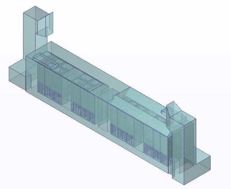
The proposed arrangement introduced conditioned air through low-level supply paths while dedicated upper return plenums captured the heated discharge air generated by the inverter cabinets.
Separating cool supply air from hot equipment discharge
The airflow configuration was developed to maintain a clear separation between the conditioned supply air and the hot air discharged from the inverter cabinets. This reduced the potential for thermal short-circuiting and allowed the HVAC system to remove heat more efficiently from the enclosure.
Low-Level Supply
Conditioned air was introduced near floor level to provide cooling air directly to the inverter equipment intake zone.
Equipment Heat Removal
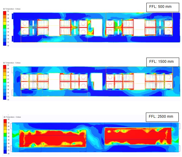
Eight inverter cabinets generated a combined peak thermal load of approximately 208 kW under the analysed full-load operating condition.
Dedicated Hot-Air Return
Upper return plenums collected the heated inverter discharge and routed it back to the HVAC system, limiting recirculation into the occupied equipment space.
Full-load thermal performance
CFD modelling was used to assess the airflow patterns, temperature distribution and interaction between the low-level supply system, inverter cabinets and upper return arrangement.
The computational domain was represented using a mesh of approximately one million elements. The HVAC system supplied approximately 8,100 L/s of conditioned air to the enclosure.
Extending the analysis from thermal performance to structural support
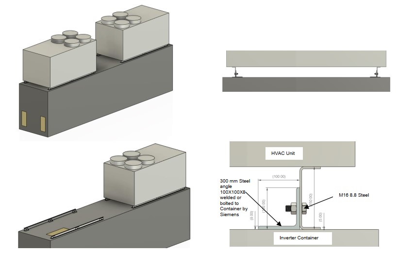
The study was extended beyond enclosure cooling to evaluate the preliminary structural support system for the rooftop HVAC equipment. Each HVAC unit was represented with an approximate operating weight of 2,230 kg.
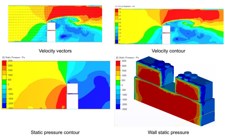
The support arrangement was also assessed for severe wind exposure corresponding to approximately 207 km/h. Wind pressures calculated from the CFD model were transferred into a finite-element model of the HVAC support brackets, allowing the effects of gravity and wind loading to be assessed together.
Wind loading and support-system verification
The proposed rooftop bracket configuration maintained a minimum calculated safety factor of 3 under the analysed combination of HVAC equipment weight and cyclonic wind load.
One coordinated workflow for thermal, airflow and structural performance
The combined modelling approach allowed the HVAC configuration, airflow distribution, thermal performance, external wind loading and preliminary structural support system to be evaluated within a single coordinated process.
From airflow concept to structural verification
By integrating HVAC design, internal CFD, external wind CFD and structural FEA, the proposed solution could be evaluated as a complete system rather than as a series of isolated design calculations.